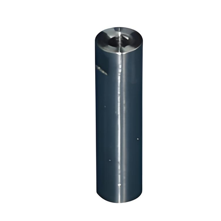
CNC Turning Vs CNC Milling — When To Use Which Process For Custom Components
What Is the Core Difference Between CNC Turning and CNC Milling?
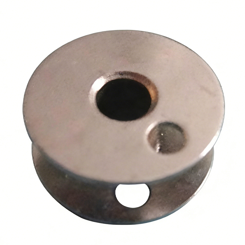
CNC turning rotates the workpiece while a stationary cutting tool removes material; CNC milling rotates the cutting tool against a stationary (or slowly index-rotating) workpiece. The opposite rotational reference defines what each process can do efficiently.
|
Property |
CNC Turning |
CNC Milling |
|
Rotational reference |
Workpiece rotates, tool is stationary |
Tool rotates, workpiece is stationary |
|
Best for |
Cylindrical, conical, rotational features |
Prismatic features, pockets, slots, contours |
|
Typical machine |
2-axis lathe (X + Z) |
3-axis, 4-axis, or 5-axis machining center |
|
Stock shape |
Bar stock, forgings, castings (round) |
Blocks, plates, near-net-shape blanks |
|
Typical tolerance |
±0.01–0.05 mm |
±0.02–0.10 mm |
|
Surface finish from cut |
Ra 0.8–3.2 μm |
Ra 0.8–6.3 μm |
Both processes are CNC-controlled, both can achieve tight tolerances, but the geometry that each can produce efficiently is fundamentally different.
When Is CNC Turning the Right Choice?
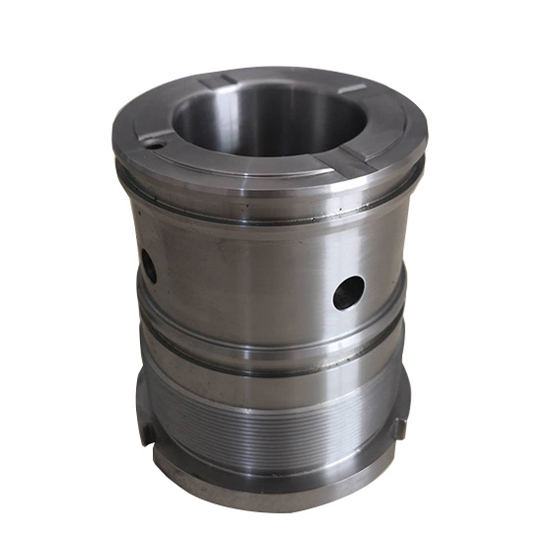
CNC turning is the right choice when the part's primary geometry is rotationally symmetric — shafts, pins, hubs, flanges, threaded fasteners, rollers, and bushings. Turning delivers fast material removal and excellent surface finish on round features.
Typical turning-only or turning-dominant parts:
Drive shafts and motor shafts
Pinion shafts and gear blanks (before gear cutting)
Hydraulic cylinder pistons and piston rods
Flanges and hubs with bolt-hole patterns
Threaded studs, bolts, and nuts
Rollers for conveyors and printing presses
Valve bodies with round ports
The economic sweet spot for turning is when the diameter-to-length ratio is roughly 1:1 to 1:10; very long thin parts (>10:1) require special steady-rest support and become uneconomic.
When Is CNC Milling the Right Choice?
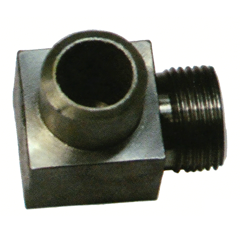
CNC milling is the right choice when the part's primary geometry is prismatic, flat, or 3D-contoured — brackets, housings, manifolds, plates, and mold inserts. Milling is the most flexible process for non-rotational features.
Typical milling-only or milling-dominant parts:
Mounting brackets and base plates
Pump and gearbox housings
Hydraulic manifolds with intersecting bores
Machine tool beds and slides
Mold inserts and die components
Heat sink plates with deep pockets
Structural components with milled pockets for weight reduction
The economic sweet spot for milling is when the bounding box fits within a standard 3-axis table (typically 600 × 400 × 400 mm for mid-size machining centers) and the part can be clamped with a standard vise or fixture.
When Are Both Processes Required?
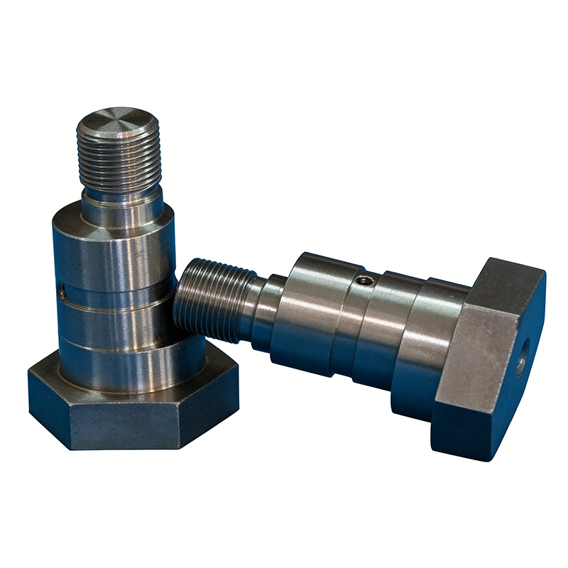
Most custom components require both turning and milling in sequence, often with a third operation (grinding) for the critical features. A typical part follows a turn-mill-grind sequence.
A representative sequence for a precision shaft with milled flats:
Turn the outer diameter to near-net shape with roughing and finishing passes.
Mill the flats, the keyway, the cross-drilled holes, and any off-center features on a machining center (after re-fixturing).
Grind the bearing journals and the seal surfaces to the final tolerance and surface finish.
Inspect with a CMM and surface roughness tester.
Chuangling Machinery's CNC Turning, CNC Milling, and CNC Grinding capabilities are structured around this turn-mill-grind workflow.
What Determines the Sequence Order?
The sequence is set by the tolerance and surface-finish requirements of each feature, not by the order of features on the drawing. Critical features are machined last so that no subsequent operation can damage them.
|
Sequence driver |
Last-operation principle |
|
Tightest tolerance (e.g., ±0.01 mm) |
Last |
|
Best surface finish (e.g., Ra 0.4 μm) |
Last |
|
Hardened surface (after heat treatment) |
Last (grinding only) |
|
Reference datum features |
Earliest, then preserved |
|
Stress-relieved features |
After stress relief |
A typical sequence for an engineering-machinery shaft:
Saw cut stock to length → Turn rough OD → Stress relief (if welded) → Turn semi-finish OD → Mill keyway, flats, cross holes → Heat treat → Grind bearing journals → Final inspection.
How Does Multi-Axis Machining Change the Decision?
Multi-axis machining (4-axis and 5-axis) blurs the turning-vs-milling line, but does not eliminate the underlying distinction. A 5-axis machining center can produce features that previously required a lathe, but the economics change.
|
Configuration |
Strengths |
Limitations |
|
3-axis mill |
Prismatic features, pockets, simple contours |
Limited access to undercuts |
|
4-axis mill |
Adds rotary axis (A or B) for side features |
Single-rotation parts only |
|
5-axis mill |
Full access to complex contours in one setup |
Higher machine cost, more programming |
|
Mill-turn (multi-axis lathe) |
Combines turning + milling on one machine |
Best for medium-complexity parts |
|
Turn-mill center |
Opposite approach: lathe with milling spindle |
Excellent for shaft-type parts |
For most custom components, the question is not "which process" but "how many operations and how many setups." Multi-axis machining reduces setups but does not replace the underlying physics.
How Are Tolerances Distributed Across the Two Processes?
Turning typically achieves ±0.01–0.05 mm in one pass; milling typically achieves ±0.02–0.10 mm; grinding achieves ±0.005 mm or better. Each process has a tolerance band that defines where it is most economical.
|
Process |
Typical tolerance |
Typical surface finish (Ra) |
Cost factor |
|
Turning |
±0.01–0.05 mm |
0.8–3.2 μm |
1× |
|
Milling |
±0.02–0.10 mm |
0.8–6.3 μm |
1× |
|
Cylindrical grinding |
±0.005–0.01 mm |
0.2–0.8 μm |
2–3× |
|
Surface grinding |
±0.005–0.01 mm |
0.2–0.8 μm |
2–3× |
If the drawing calls for ±0.005 mm on a diameter, the feature is a grinding feature regardless of how the rest of the part is made. If the drawing calls for ±0.05 mm, turning is usually sufficient and grinding is wasted cost.
What Equipment Does Chuangling Operate?
Chuangling Machinery operates a CNC equipment fleet that covers the full turn-mill-grind workflow, with multi-axis capability for complex components. The production equipment list is documented on the Production Equipment page.
Typical equipment categories for turn-mill-grind work:
CNC lathes (2-axis and multi-axis) for turning.
Vertical machining centers (3-axis) for prismatic milling.
Horizontal machining centers (4-axis) for high-volume prismatic work.
5-axis machining centers for complex contours.
Cylindrical grinders for shaft finishing.
Surface grinders for flat reference surfaces.
CMMs and surface roughness testers for inspection.
The combination of equipment and engineering capacity is what determines whether a part can be made in one setup, two setups, or five. Chuangling's CNC Turning page documents the turning capacity; the CNC Milling page documents the milling capacity.
What Are Common Selection Errors?
Five errors recur across engineering teams when they choose between turning and milling without a process review. Each is preventable with a 15-minute process review at the drawing stage.
Milling a feature that should be turned. A round boss with a center hole is faster and cheaper on a lathe; milling it adds cycle time.
Turning a feature that should be milled. A rectangular pocket on a round part is faster and cheaper on a mill; turning it requires a special form tool and many passes.
Specifying grinding where turning or milling is sufficient. A ±0.01 mm tolerance is achievable on a turning center with high-end slides; specifying grinding adds 2–3× the cost.
Forgetting the heat-treatment step. A part that needs hardening must be machined in the soft state, hardened, then ground. Skipping the grinding step leaves tolerances out of spec.
Multiple setups where one setup would suffice. A multi-axis machine can produce features in one setup that previously required three; the savings are in setup time, not cycle time.
How Is Process Selection Documented?
Process selection is documented in a manufacturing plan that lists each feature, the process that produces it, the machine, the tooling, and the inspection method. The plan is the contract between engineering and production.
A manufacturing plan typically includes:
A feature-by-feature process list.
The sequence of operations.
The machine and tooling for each operation.
The inspection points and the inspection method.
The cycle time estimate per operation.
The total cycle time and the cost roll-up.
For complex parts, the plan is reviewed by engineering, production, and quality before the first piece is cut. Chuangling's CNC Turning and CNC Milling workflows include a manufacturing plan as a standard deliverable for custom orders.
Frequently Asked Questions
Q: Can a CNC lathe do everything a CNC mill can do?
A: No. A CNC lathe can perform milling, drilling, and tapping with live tooling and a subspindle or turret-mounted milling spindle, but it is mechanically constrained for large prismatic features, deep pockets, and high-spindle-speed milling. A 5-axis machining center can produce many turned features, but at a higher machine cost.
Q: What is the smallest diameter a turning center can hold?
A: Standard turning centers can hold diameters down to a few millimeters with collets or chucks. Swiss-type turning centers (sliding headstock) can produce parts down to 1 mm diameter with very high precision. The holding method — collet, chuck, or steady rest — is matched to the part's length-to-diameter ratio.
Q: What is the largest part a CNC mill can hold?
A: Standard 3-axis machining centers handle parts up to roughly 1 m × 0.6 m × 0.5 m on the table. Larger parts require a traveling-column machining center or a gantry-type machine. For parts that exceed the standard envelope, plan for setup on multiple fixtures or for a custom machine.
Q: Is CNC milling more expensive than CNC turning?
A: Not necessarily. The cost depends on the part geometry, the material, the tolerance, and the batch size. A turned shaft can be more expensive than a milled bracket if the shaft requires exotic material, deep drilling, or a tight concentricity requirement.
Q: What is mill-turn machining?
A: Mill-turn machining is a hybrid process where a single CNC machine combines a turning spindle and a milling spindle (often on the same turret or as a separate B-axis head). It allows the part to be turned, milled, drilled, and tapped in one setup. Mill-turn is most economical for medium-complexity parts with both rotational and prismatic features.
Q: How do I choose between a 3-axis mill and a 5-axis mill?
A: Choose a 3-axis mill for parts that fit in one setup on a standard table; choose a 5-axis mill for parts that require access to multiple faces, undercut features, or complex contours in one setup. The 5-axis mill saves setup time but has higher per-hour cost.
Q: Can a part be made entirely on a lathe?
A: Yes, if every feature is rotationally symmetric or accessible from the spindle axis. The part can be turned, faced, grooved, threaded, knurled, drilled (on center), and — with live tooling — milled and cross-drilled. Off-center features that are not accessible to live tooling must be done on a separate milling machine.
Q: When should I specify grinding instead of turning for a tolerance?
A: Specify grinding when the tolerance is ±0.005 mm or tighter, when the surface finish must be Ra 0.4 μm or better, when the part is hardened, or when the roundness or cylindricity must be held to micron level. Below these thresholds, grinding is more economical than high-precision turning.
Q: How does Chuangling choose between turning and milling for a new RFQ?
A: Chuangling's engineering team reviews the part drawing, the 3D model (if available), the material, the batch size, and the tolerance requirements. The team returns a manufacturing plan that identifies the primary process, the secondary processes, the machine list, and the cycle time estimate.
Conclusion
CNC turning and CNC milling are complementary, not competing, processes. The right selection matches the part's geometry to the process's strength, then sequences the operations to protect the critical tolerances. Chuangling Machinery's CNC Turning, CNC Milling, and CNC Grinding capabilities cover the full turn-mill-grind workflow for custom components across the Engineering Machinery Components, Rail Transit Components, Packaging Machinery Components, Textile Machinery Components, and Mechanical Equipment Components families. Pair the process selection with the Production Equipment review and the Company capability summary for a complete procurement picture.