Motor Housing Machining: Holding Bore Alignment Through The Whole Process
A motor housing looks like a simple shell until the first prototype runs. Then the noise appears, or the bearing runs hot, or the rotor drags at one point in its rotation. In most of those cases the drawing was met on the bench and the problem is buried in the stack-up between two bores, a flange face and a bearing seat that were machined in different setups.
Motor housing machining is therefore less about removing material and more about deciding which features must be cut in the same clamping, which must be cut after stress has been released, and which can be finished last without the part moving. This article walks through that decision chain for aluminum and cast iron housings, using the process sequence Chuangling runs on turned and milled motor housings.
What the Housing Actually Has to Guarantee
An electric motor housing carries four functions at once: it protects the winding and rotor, it positions the stator stack, it holds the bearing bores in line, and it conducts heat out of the laminations. Each function maps to a different set of dimensions, and they are not equally forgiving.
Bore alignment
The two bearing seats, or the bearing seat and the end shield spigot, define the rotor axis. If they are offset, the air gap becomes uneven; if they are skewed, the rotor preloads one bearing. A common production callout is 0.02–0.05 mm concentricity between the drive-end and non-drive-end seats, measured over the full bore length rather than at a single section.
Roundness and fit
The stator stack is usually a press or shrink fit into the housing bore. A bore that is round on the CMM but tri-lobed after clamping will still distort the laminations. Roundness of 0.01–0.02 mm and cylindricity over the stack length matter more than the absolute diameter, because the fit is controlled by the stack OD anyway.
Flange and mounting faces
The mounting flange sets how the motor sits in the machine. Flatness of 0.05 mm and perpendicularity of 0.03 mm to the bore axis are typical, and they are the features most often lost when a part is re-chucked for a second operation.
|
Feature |
Typical callout |
Why it fails in production |
|
Bearing bore diameter |
IT6–IT7 |
Tool wear not compensated across the batch |
|
Bore-to-bore concentricity |
0.02–0.05 mm |
Two setups, one soft jaw, no alignment check |
|
Bore roundness |
0.01–0.02 mm |
Clamping pressure on a thin wall |
|
Flange flatness |
0.05 mm |
Part released before finishing, then sprung |
|
Flange perpendicularity to axis |
0.03 mm |
Face cut in a separate op without indicating the bore |
|
Bore surface finish |
Ra 1.6 µm |
Feed too high on the finishing pass |
A Process Route That Survives Production
The route below is the one used for housings with a through bore and a bolted or welded flange. It assumes a casting or a billet, and it deliberately separates roughing from finishing by a stress-relief step.
Op 10 — rough turn and face
Rough the OD, the bore and the reference face with 1.5–2 mm of stock left on diameter. The goal is to remove the decarburized skin and the bulk of the material, not to hold tolerance. On castings, this is also where you find out whether the wall thickness is consistent enough to hold the bore concentric later.
Op 20 — stress relief or natural ageing
Aluminum housings machined from billet move after roughing because the residual stress from the plate is released as material leaves. A stress-relief cycle between roughing and finishing, or a controlled ageing period, removes most of the movement. Cast iron housings benefit from a normalizing step if the foundry did not already do it.
Op 30 — mill flange, terminal box face and mounting pads
Mill in a single clamping: flange face, terminal box face, mounting pads and any tapped bosses. Cutting these together keeps their relationship to each other, and it leaves the bore as the only feature that has to be re-established later.
Op 40 — finish bore and finish face in one clamping
This is the operation that decides whether the motor runs quietly. Indicate on the milled flange face or on the rough bore, then finish the bore, the counterbore and the face in the same setup. Turning the face and the bore in one clamping removes the perpendicularity error that appears when the face is cut in a separate operation.
Op 50 — drill, tap and deburr
Cross holes, drain holes and tapped bosses come after the bore is finished, because drilling into a finished bore distorts it locally. Deburring is done by hand on the bore edges and by brush on the cross holes; a burr left at a bearing seat shoulder will misalign the bearing during assembly.
Op 60 — wash, dry and inspect
Wash before inspection, not after. Chips trapped in a cross hole show up as a bore scratch on the customer's line, and that is a return that costs more than the wash station.
Where Clamping Distortion Comes From
Thin-wall aluminum housings are the classic case. A three-jaw chuck tightened to hold a 2 mm wall will make the bore tri-lobed by 0.03–0.06 mm, and the part springs back when it is released — but not completely. The bore measures round off the machine and out of round in the assembly fixture.
|
Distortion source |
Symptom |
Countermeasure |
|
Three-jaw chuck on thin wall |
Tri-lobed bore, ovality after release |
Pie jaws or a collet with full circumference contact |
|
Excessive clamping pressure |
Bore size drifts between load and unload |
Torque-controlled chuck, pressure regulator |
|
Fixture over-constraint |
Part rocks, face not flat |
Three-point support, sequence-controlled clamps |
|
Heat from heavy finishing pass |
Size grows during the cut |
Coolant through the tool, lighter finish pass |
|
Residual stress in billet |
Bore moves 24–48 h after machining |
Stress relief between roughing and finishing |
The practical rule is to finish the bore with the lowest clamping force that still holds the part, and to inspect the part both clamped and free. If the two readings differ by more than a third of the tolerance, the fixture is doing more work than the cutting tool.
Matching the Housing to the Motor Build
A housing for a small servo motor and a housing for a 55 kW industrial motor do not need the same process. For low-volume and prototype work, a billet housing turned and milled from 6061-T6 or 6082-T6 is often cheaper than tooling a casting, and it gives the design team room to move the mounting pattern without paying for a new pattern.
For series production, a casting amortizes the pattern quickly and gives a better stiffness-to-weight ratio in the flange. Chuangling machines both: billet housings on CNC turning and machining centres, and cast housings where the foundry supplies the blank and the machining is done in-house. Because the same shop cuts the flange, the bore and the terminal box face, the alignment between them is a fixturing decision rather than a supply-chain negotiation.
For housings with a cooling jacket, the leak test belongs in the same route. Pressure-test the jacket after welding and before the final bore finish, so a leaking weld does not scrap a part that already carries a finished bearing seat.
Inspection That Catches the Real Failure
A CMM report on a temperature-soaked part in a metrology room will pass almost anything. The checks that catch production problems are simpler:
• Bore size measured with an air gauge or a bore gauge at three heights and two directions, at the same temperature as the machine.
• Concentricity checked with a mandrel between the two seats, not by comparing two independent CMM axes.
• Flange flatness checked on a surface plate with the part free, not clamped.
• Roundness checked on the part as it comes off the machine, before it has time to relax.
What to Put in the RFQ
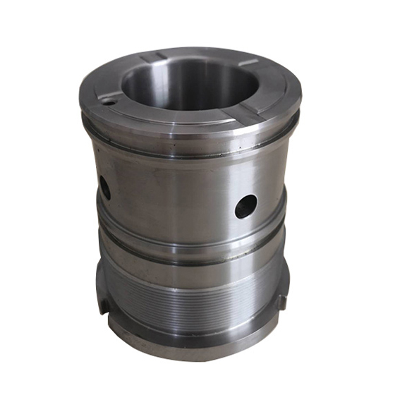
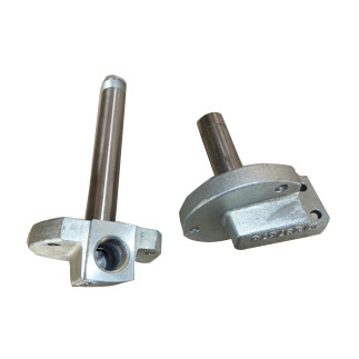
Customized CNC Machining for Motor Housing
The quotation for
motor housing machining depends far more on the drawing package than on the tonnage of aluminum. Three items change the price most: whether the bore and the flange face can be cut in one clamping, whether a stress-relief step is required, and whether the tolerance is specified on the diameter only or on the geometric relationship between features.
Send the housing drawing with the datum scheme marked, the blank route (billet, casting or forging), the annual quantity and the expected batch size. Chuangling quotes motor housing machining against that package and returns a process route showing which operations are done in which clamping, so the customer can see where the alignment is established before the first chip is cut. A first article from Chuangling includes bore and flange readings taken with the part free, which is the measurement that predicts how the motor will assemble.