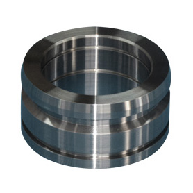
A forging is bought for what happens inside the metal, and then it is machined for what happens on the surface. The two are planned together or not at all. A blank with generous stock and no datum will machine into a part that is dimensionally correct and structurally compromised, because the machining cut away the grain flow that justified the forging in the first place.
This article covers the decisions that sit between the forge and the finished part: how much stock to leave, where to hold the part, which heat treatment goes before machining and which goes after, and how to inspect a machined forging without pretending it is a bar-stock part.
Why Forge and Then Machine
Forging deforms solid metal under compressive force, which refines the grain and turns the grain flow to follow the part contour. The result is higher fatigue strength and better toughness than the same alloy cut from bar, particularly in the direction perpendicular to the working load.
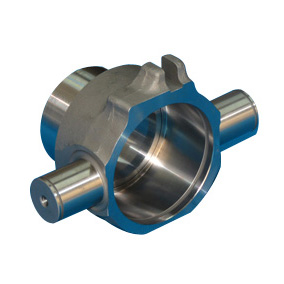
Rail Transit
Casting and machining can both produce the same geometry. What they cannot do is produce the same grain structure. For a hydraulic cylinder head, a connecting component or a rail transit bracket, that difference is the reason the drawing specifies a forging. The economics of machined forgings are therefore set at the blank stage, not at the machine.
Where the advantage disappears
The advantage is lost if the machining removes the flowed grain at the highest-stress section, or if the forging is normalized after machining and the surface is left with a decarburized layer. Both happen when the blank is bought to a price rather than to a drawing.
Stock Allowance: The Number That Sets the Cost
Machining allowance on a forging is a compromise. Too little and the part cannot clean up after the forging tolerance and the scale; too much and the shop spends time turning air, and the grain flow near the surface is cut away.
|
Blank size (max dimension) |
Typical allowance per side |
Reason |
|
Up to 100 mm |
1.5–2.5 mm |
Tight die tolerance, light scale |
|
100–250 mm |
2.5–4.0 mm |
Die wear, draft, mismatch |
|
250–500 mm |
4.0–6.0 mm |
Heat distortion, larger mismatch |
|
Over 500 mm |
6.0–10.0 mm |
Distortion and handling damage |
The allowance also has to absorb draft angle, die mismatch, flash-line offset and heat-treatment distortion. A forging with a 3 mm mismatch between die halves needs at least that much stock on the affected faces, or the part will not clean up on one side.
Datum selection on a forged surface
A forged surface is not a datum. It carries draft, scale and mismatch, so indicating on it transfers those errors into the machined features. The practical approach is to machine a datum pad or face in the first operation, then use that machined face for every subsequent operation.
For a part with no natural flat, two options work: machine a set of temporary pads that are removed later, or hold the part in a fixture that locates on the die parting line and the flash land. The second is cheaper per part and needs a fixture that is built for the specific forging.
Heat Treatment: Before or After Machining
The sequence matters more on forgings than on bar stock, because the forging process leaves residual stress and a decarburized skin.
Normalizing or annealing before machining
This is the standard route for closed-die forgings. Normalizing refines the grain after forging, softens the part for machining, and — critically — releases the
forging stress before the first cut. Machining a stressed forging produces a part that moves after the final operation.
Quenching and tempering before machining
For medium-carbon and low-alloy steels such as 42CrMo4, quench and temper to the required hardness before machining, then machine with carbide or CBN tooling. Machining after hardening is possible up to about 45 HRC with hard turning, and beyond that grinding is the practical route.
Stress relief after rough machining
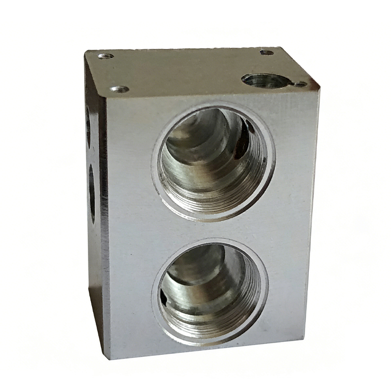
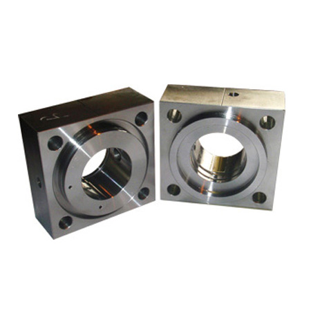
For thin-wall or asymmetric parts, a stress-relief cycle between roughing and finishing removes the stress that roughing itself introduces. On a hydraulic valve block or a thin flange, this step is what keeps the part flat after the last cut.
The Machining Sequence
The sequence below suits a forged part with a bore, a flange and a sealing face — a hydraulic cylinder head, a cylinder block or a valve body.
|
Op |
Operation |
Key control |
|
10 |
Incoming inspection of the forging |
Dimensions, hardness, surface defects, UT where specified |
|
20 |
Normalize or Q&T |
Hardness range, distortion |
|
30 |
Rough machine, leave 0.5–1.0 mm |
Stock distribution checked, not just size |
|
40 |
Stress relief (if required) |
Distortion after relief measured |
|
50 |
Semi-finish, establish datums |
Datum face flatness, perpendicularity |
|
60 |
Finish bore and sealing faces in one clamping |
Roundness, Ra, perpendicularity |
|
70 |
Drill and tap |
Position, burr control |
|
80 |
Final inspection |
CMM, hardness, surface, NDT where specified |
Two operations carry most of the risk. Rough machining decides whether the finished part still has enough grain flow and whether the stock is distributed evenly. Finish boring decides whether the part seals.
Machining the flash line
The flash line is the seam where the dies met, and it is usually the hardest and dirtiest part of the surface. Interrupted cuts across the flash line destroy inserts, so the first pass should cut below it rather than through it, or the flash should be ground off before machining.
Defects That Only Appear After Machining
Some forging defects are invisible until the first cut, and by then the part has cost money. Knowing which defect produces which machining symptom is what allows a shop to reject a batch early instead of scrapping finished parts.
|
Forging defect |
Machining symptom |
Action |
|
Decarburized surface layer |
Hardness low at the surface after machining |
Specify depth of decarb on the purchase order |
|
Scale pits |
Black spots that do not clean up |
Extra allowance, or shot blasting before machining |
|
Die mismatch |
Uneven stock, one side breaks through |
Reject the batch, adjust the die |
|
Internal porosity or piping |
Bore breaks into a void |
UT on the blank for pressure-critical parts |
|
Hard spots from segregation |
Tool chipping, poor finish in one area |
Anneal, or accept slower cutting with ceramic inserts |
|
Residual stress |
Bore ovality after final cut |
Stress relief between roughing and finishing |
Inspection of a Machined Forging
Dimensional inspection is the same as for any machined part; the difference is the material verification that has to accompany it.
• Material certificate with heat number, chemical composition and mechanical properties, traceable to the batch.
• Hardness survey at three locations on the part, after heat treatment and after machining, because the surface can differ from the core.
• Ultrasonic inspection on pressure-retaining forgings, before machining where possible, so a reject does not consume machining hours.
• Magnetic particle or dye penetrant on finished surfaces where the drawing requires it.
• Dimensional report against the marked critical characteristics, with the datum scheme stated.
Chuangling
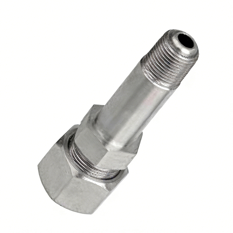
machines forged blanks into hydraulic cylinder heads, guide bushings, cylinder blocks, pipe locks, transition joints and rail transit components, with forging, normalizing, machining and inspection in one supply chain. That matters most for parts where the grain flow direction has to survive the machining sequence, because the shop that cuts the part also decides how much of the forging's advantage remains in the finished component. Chuangling keeps the forging source and the machining route on one job card, so the grain flow direction is a documented decision rather than a habit.
What to Send With the Enquiry
The enquiry needs the finished drawing, the forging drawing or the specification of the blank, the material standard, the heat treatment requirement, the annual quantity and any NDT requirement. If the forging is customer-supplied, state the condition it arrives in — as-forged, normalized or pre-machined — because that decides the first operation. Chuangling confirms the blank condition before quoting, since a pre-machined blank removes an operation and an as-forged blank adds one.
Chuangling quotes machined forgings against the finished drawing and the blank condition together, and returns a process route that names the heat treatment steps, the number of setups and the inspection points. For buyers moving a part from bar stock to forging, that route is also the cost comparison: it shows where the forging saves material and where the extra operations have to be paid for.