A
grinding machine can produce one part to ±0.002 mm on the first attempt. The question that decides whether a grinding supplier is useful is whether the hundredth part is also within ±0.002 mm, and whether the report that comes with it shows that. CNC grinding is a process-control problem disguised as a finishing operation.
This article looks at the four methods that cover most work, the variables that move size across a batch, and the checks that make a capability claim verifiable rather than anecdotal.
The Four Methods and What Each Owns
|
Method |
Typical feature |
Tolerance |
Surface finish |
Notes |
|
Cylindrical OD grinding |
Shafts, bearing seats, pins |
IT5–IT6, ±0.003 mm |
Ra 0.2–0.4 µm |
Work between centres or in a chuck |
|
Internal grinding |
Bores, bushings, housings |
IT6–IT7, ±0.005 mm |
Ra 0.4 µm |
Wheel diameter limits the smallest bore |
|
Surface grinding |
Flats, faces, plates |
0.005 mm flatness |
Ra 0.4 µm |
Magnetic chuck can distort thin parts |
|
Centerless grinding |
Pins, bushings, valve stems |
IT6, ±0.005 mm |
Ra 0.2–0.4 µm |
High volume, no centres needed |
Method selection is driven by geometry, not preference. A bore under 20 mm diameter needs a small wheel, which limits wheel speed and stiffness; a thin plate on a magnetic chuck needs blocking or a vacuum fixture, or it will spring when released.
Cylindrical grinding: the workhorse
Most
CNC grinding capacity is cylindrical. The part rotates against a wheel, and the size is controlled by the infeed. Two setup details decide accuracy: the centres or the chuck jaws, and the steady rest if the part is long.
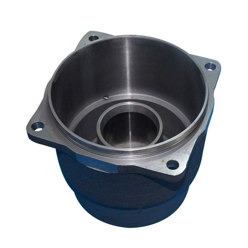
Transit Rail Grinding
A shaft held between centres with worn centre holes will grind a lobed profile that repeats every revolution. Re-lapping the centres is a five-minute operation that prevents a day of investigation. Chuangling checks centre condition at every setup change on cylindrical work.
Internal grinding: the stiffness problem
An internal spindle is a slender cantilever, and the wheel is small. Deflection shows up as a tapered bore or a bore that is oversize at the entry. Reducing the depth of cut per pass, increasing the wheel speed and using a shorter spindle extension are the three levers.
What Moves Size Across a Batch
On a stable process, size drifts slowly and predictably. On an unstable one, it moves with the wheel, the coolant and the operator.
|
Variable |
Effect on size |
Control |
|
Wheel wear |
Size grows as the wheel loses form |
Dressing interval, in-process gauging |
|
Thermal growth of the machine |
Size drifts in the first hour of a shift |
Warm-up cycle, temperature-stable coolant |
|
Coolant concentration and flow |
Burn and finish change, size drifts |
Refractometer check, flow switch |
|
Dressing depth and speed |
Wheel sharpness, effective size |
Fixed dress program, not operator judgement |
|
Part hardness variation |
Size and finish vary between batches |
Incoming hardness check on hardened stock |
|
Fixture wear |
Taper and roundness change |
Fixture inspection on a schedule |
The two that account for most out-of-tolerance parts are wheel wear and thermal drift, and both are solved by the same thing: in-process or post-process gauging that feeds back to the control.
In-process gauging
A gauging head that measures the part while it is being ground lets the control stop the cycle at the target size rather than at a programmed infeed. That removes wheel wear from the size equation. It costs more than a manual gauge, and on a batch of 500 hardened bearing seats it pays for itself in scrap alone.
Where in-process gauging is not fitted, the practical alternative is a first-off, a mid-batch check and a size trend chart. A trend chart that shows the size walking in one direction tells the operator to dress; a chart that scatters tells them to look at the fixture. Chuangling keeps the trend chart with the batch record, so the next order starts from known wheel behaviour.
Stainless Steel on a Grinding Machine
Stainless is where grinding behaviour differs most from carbon steel. Austenitic grades work-harden, have low thermal conductivity and tend to load the wheel.
|
Issue |
Mechanism |
Countermeasure |
|
Wheel loading |
Soft, gummy chips fill the pores |
Open wheel structure, coarser grit, higher coolant pressure |
|
Work hardening |
Surface hardens under the wheel, then tears |
Sharp wheel, adequate depth of cut, avoid rubbing passes |
|
Heat concentration |
Low conductivity keeps heat at the surface |
High coolant volume, directed at the contact zone |
|
Residual stress |
Grinding adds tensile stress to a sensitized surface |
Light finishing passes, stress relief where specified |
|
Contamination |
Carbon steel particles embed in stainless |
Dedicated wheel and coolant for stainless work |
Grinding stainless is a matter of keeping the wheel cutting rather than rubbing. A wheel that is allowed to glaze will work-harden the surface, and the next pass will then cut through a hardened layer, which produces both a poor finish and a stressed surface. Chuangling runs stainless work on a dedicated wheel and coolant circuit to keep carbon steel particles out of the surface.
Burn, Cracks and the Checks That Reveal Them
Grinding burn is a subsurface change that the part survives dimensionally. Three checks catch it.
Visual and colour inspection finds the severe cases: straw, brown or blue discoloration on a ground face.
Nital etch reveals tempering and rehardening zones that are invisible. It belongs in the control plan for any ground surface carrying a fatigue load, such as a bearing seat or a rail transit axle component.
Barkhausen noise or X-ray diffraction measure residual stress directly, and are used where the specification calls for it rather than as routine production checks.
A grinding process that produces a good finish but leaves a burnt subsurface is worse than a process that produces a slightly rougher finish without burn, because the burnt part passes inspection and fails in service.
Capability, Not Just Conformance
A conformance report says the parts were inside tolerance. A capability study says the process will stay inside tolerance. For a grinding operation, the difference is measurable with 30 consecutive parts.
• Measure all 30 on the same gauge, at the same temperature.
• Calculate the mean and standard deviation.
• Compare the tolerance band to six standard deviations. A process with a Cpk of 1.33 uses about three quarters of the tolerance band for normal variation, which leaves room for the drift between dressing cycles.
• Plot the values in production order, not in size order, so drift is visible.
If the trend shows size walking between dressings, the answer is more frequent dressing or in-process gauging, not a tighter tolerance on the drawing.
Specifying CNC Grinding Work
Four inputs are enough to quote: the feature to be ground, the tolerance and finish, the material and hardness, and the batch size. Add the pre-grinding condition — how much stock is left and whether the part is hardened — and the cycle time can be estimated.
Chuangling grinds shafts, bushings, bores, flats and rail transit components on
CNC grinding equipment, with milling and turning in the same plant so the grinding allowance is set by the operation that will remove it. For stainless parts, the wheel and coolant are dedicated to the material rather than shared with carbon steel work, which is the detail that decides whether the finish is consistent across a batch.